 English


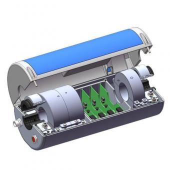
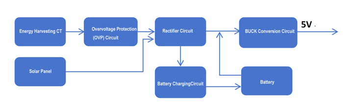
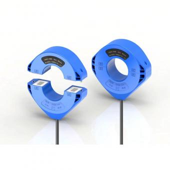
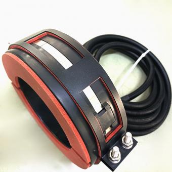
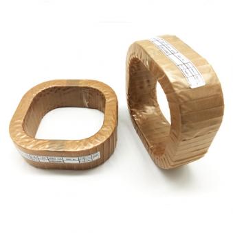
The overhead output power supply device is an open structure, with an aluminum alloy case, it's suitable for overhead transmission lines with a voltage of 35KV and above. The product obtains a low voltage and safe working power supply through the principle of electromagnetic induction, and provides electrical power to the monitoring device with the assistance of photovoltaic panels.
Key Properties:
1. Strong power supply capability
2. Integrated design
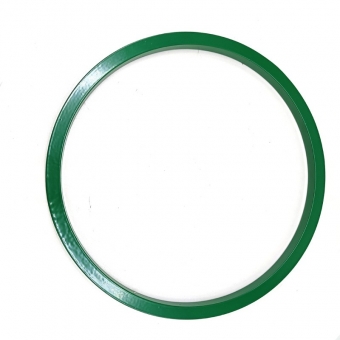
3. Conductive rubber buckle
Application:
Reference Items:
Technical Parameter
Technical Parameter
Work Power
Energy Harvesting Power Unit
Output Voltage 5V, Output Power 15W
Lithium battery
Standard Voltage 6.4V, Standrad Capacity 6AH
Power Supply CT
Energy Harvesting Capability
20A >4W 10A >1.5W
Protection Level
IP67
Inrush Current
31.25KA/4S 15KA/2S
Continuous Current
1500A
Solar Panel
Rated Power
6.0W(±5%)
Nominal Voltage
12V(±10%)
Conversion Efficiency
22%
Current Sensor
Power Frequency Current
Measurement Range: 15KA
Traveling Wave Current
Measurement Range: 5KA
Residual Risk Current
Measurement Range: 5A
Application Scope
Voltage Class
35kV and above transmission lines
Gross Weight
<5kgs
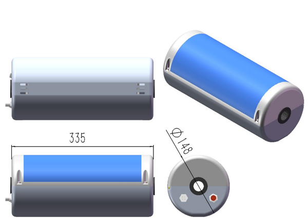
Dimension
OD 142mm, Length 315mm
Working Conditions
Ambient Temperature
-40°C ~ +85°C
Relative Humidity (RH)
1% ~100%
Altitude
≤5500m
Frequency Range: 20 ~1 K
Accuracy: <1% ±5A
Frequency Range: 1K ~ 2M
Accuracy: <1% ±2A
Frequency Range: 10kHz ~ 5MHz
Accuracy: <5% ±0.01A
Technical Index
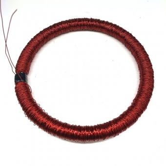
A). Inductive Energy Harvesting Current Transformer
1. Test with the power supply board, adjust the single current, and measure the corresponding maximum output power through electronic load.

Single Current / A
Power Output of Single CT
5A
0.37W
10A
1.29W
15A
2.58W
20A
4.16W
2. Inductive Energy Harvesting CT Winding Details
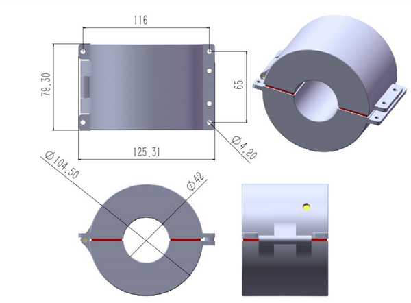
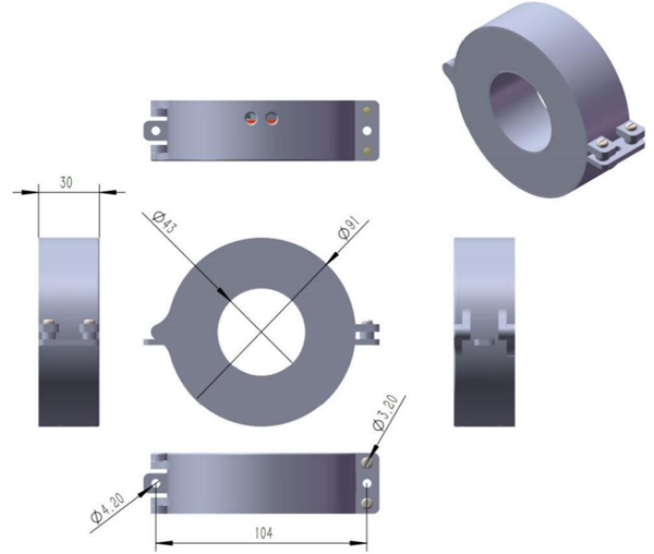
3. Inductive Energy Harvesting Dimension (mm)
1. Definition of Power Supply Board Terminals
Definition of Power Supply Board Terminals
Energy Harvesting CT Input
VH3.96 terminal, regardless of positive or negative polarity
Solar Panel Input
XH2.54-2P terminal, red positive &black negative, input voltage range o 10-24V
Adapter Input
XH2.54 terminal, the main purpose of the adapter input is to charge the battery inside the device or directly supply DC power for testing before shipment. It can also be used as a backup solar panel input in DC input lines.
Switch Interface
XH2.54-4P terminal, battery switch, S - and S+connection switches, LED and G connection switch indicator lights
Battery Interface
The battery input terminal is XH2.54, distinguishes between positive and negative poles. Rated battery voltage 7.2V, charging cut-off voltage is 8.4V. The Max. charging current 0.8A
Power board output
XH2.54-5P terminals are defined as:
+5V (DC 5V power supply)
GND (power ground)
BAT_V (battery voltage)
CF_V (photovoltaic panel voltage)
CT_V (rectified voltage after taking power from CT)
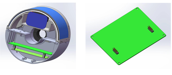
2. Energy Harvesting CT Working Principle Diagram
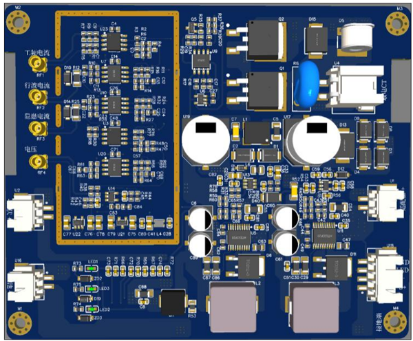
3. 3D diagram of power supply board and signal adjustment board
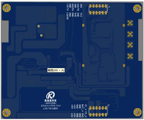
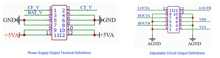
C). Pin Definition
|
Power Supply Output Terminal Definitions |
|
Adjustable Circuit Output Definitions |
||||
|
Item |
Mark |
Definitions Decsription |
|
Item |
Mark |
Definitions Decsription |
|
1 |
CF_V |
Solar Panel Voltage Divider Ratio Measurement 6.1:1 |
|
1 |
GND |
Ground |
|
2 |
CT_V |
Energy Harvesting CT Voltage Divider Ratio Measurement 31:1 |
|
2 |
VLS |
Power Frequency Voltage Output |
|
3 |
BAT_V |
Battery Voltage Divider Ratio Measurement 6.1:1 |
|
3 |
HOUTB |
Hazardous Current Output |
|
4 |
GND |
Ground |
|
4 |
GND |
Ground |
|
5 |
GND |
Ground |
|
5 |
GND |
Ground |
|
6 |
GND |
Ground |
|
6 |
VHS |
Traveling Wave Voltage Output |
|
7 |
GND |
Ground |
|
7 |
HOUTA |
Traveling Wave Current Output |
|
8 |
GND |
Ground |
|
8 |
GND |
Ground |
|
9 |
+5V |
Power Output 5V |
|
9 |
GND |
Ground |
|
10 |
+5V |
Power Output 5V |
|
10 |
GND |
Ground |
|
11 |
+5V |
Power Output 5V |
|
11 |
LOUTA |
Power Frequency Current Output (15KA) |
|
12 |
+5V |
Power Output 5V |
|
12 |
LOUTB |
Power Frequency Current Output (15KA) |
D). Power Frequency Traveling Wave Hazardous Current CT
1. Technical Parameter
Item
Power Frequency Current
Traveling Wave Current
Hazardous Current
Current Range
15KA
6KA
1mA ~ 5A
Frequency Range
20 ~1KHz
1K ~ 2MHz
10K ~ 5MHz
Accuracy
±5%±5A
±5%±2A
±10%±0.01A
Three in one integrator
Supply Voltage
3.3V
Rising Voltaeg
1.65V
Loss
~ 8mA
Corresponding output
15KA/1.1V (Valid Value)
6KA/1.5V(Peak Value)
5A/1.1V (Valid Value)
2.Terminal Remark
Default Terminal MMCX
3. CT Size (mm)
Dimension:
1. Complete Devise Size (mm)
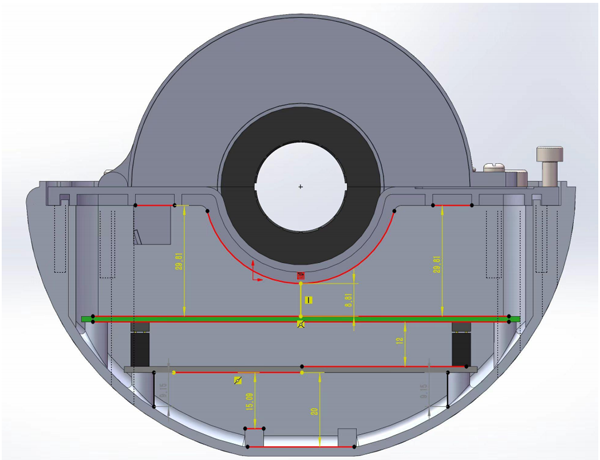
2. PCB layout space
Height limited (mm)

As an leading manufacturer of induction power supply products, Coilcore provides quality services to customers with high-performance products and one-stop solutions. By leaving a message below to get more details about Inductive Power Supply Current Transformer quickly!
If you are interested in our products and want to know more details,please leave a message here,we will reply you as soon as we can.
IP67, excellent waterproof performance, works well even under water condition 3 days.
CT power supply (induction power supply), is a device that uses CT installed on power lines to obtain power through electromagnetic induction principle. It consists of two parts: the power supply CT (energy transformer) and the power conversion module (converting the electrical energy obtained by CT into the required DC voltage). Our Energy Harvesting current transformer, IP68 design, hasas excellent waterproof performance and can work for a long time in outdoor water environments.
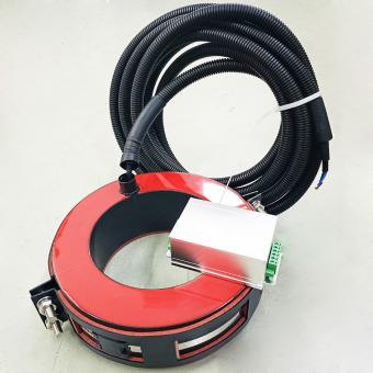
CT power supply (induction power supply), is a device that uses CT installed on power lines to obtain power through electromagnetic induction principle. It consists of two parts: the power supply CT (energy transformer) and the power conversion module (converting the electrical energy obtained by CT into the required DC voltage). Our Power Conversion Module has intelligent power management based on energy harvesting, with conversion efficiency ≥90%, IP68 design perfect for outdoor application.
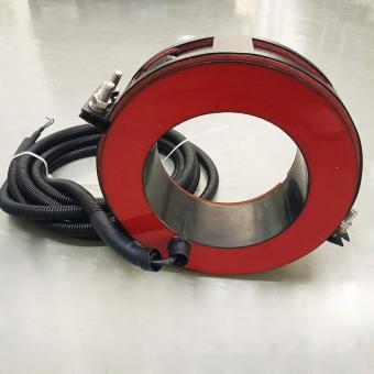
The inductive Power Supply Current Transformers usually installed outdoors or in underground cable trenches and tunnels, with the working environment maybe raining, moisture, water accumulation. Once the split core CT with poor structure, the core cutting surface will be easy to rust, which affects the power supply ability, increasing working noise, even can't work. After long time R&D, our Coilcore's latest inductive Power Supply Current Transformers reach IP68 standard, which can achieve zero noise operation.
High saturate induction reduce volume of transformers, popular in inverter power application.
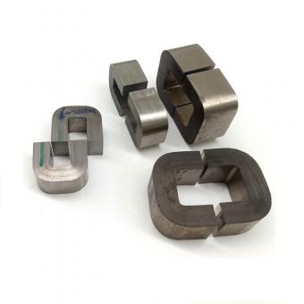
High Saturation Flux Density amorphous C Cutting Core, standard AMCC series and OEM size design supportted, popular in PFC Choke coils.
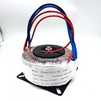
This is an isolation transformer that separates primary and secondary... In another word, it's full isolation transformer,not an autotransformer.
High accuracy nanocrystalline cores, for low voltage instrument current transformer, medium voltage instrument current transformer, high voltage instrument current transformer in industry application.
For inquiries about our products or pricelist, please leave to us and we will be in touch within 24 hours.


 Call At :
Tel : +86-20-85649266
Fax : +86-20-85649263
 Email Us :
Email : derful@coilcore.com
 Address :
A402 Zhuangyuangang Industry Park, No.186 Qishan Road, Tianhe District, Guangzhou 510663
© Copyright: 2025 Guangzhou Amorphous Electronic Technology Co.,ltd. All Rights Reserved. 粤ICP备2021057165号

IPv6 network supported