The Design and Manufacture Skiss of Plannar Transformer (Inductor)
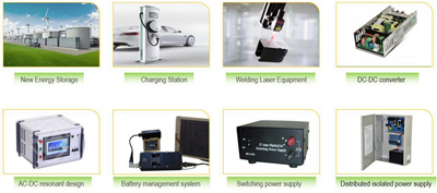
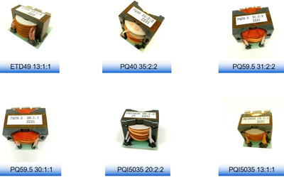
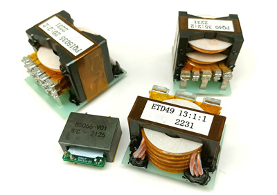
The planar core's successful development, a planar transformer (inductor) design was realized. Comparing to traditional transformer, the planar transformer (inductor) winding is a planar structure, have priority including: high current density, high efficiency, low leakage inductance, excellent heat conduction, low EMI radiation, small size, The parameter repeatabiltiy is good, wide operating frequency range, wide operating temperature range, good insulation. The Planar transformer’s (inductor’s) power from 5W to 20KW, frequency from 20KHz to 2MHz, efficiency up to 98%. It’s widely application in telecommunications, welding machines, computers, medical electronics, industrial control, networking, security systems and electronic equipment.

With decades experience in plannar transformer (inductor) manufacture, here we have a brief summarize the planar transformer (inductor) from four aspects: material selection, structure design, production process, and electrical safety regulations.
Material Selection
1. To meet temperature rise & efficiency request, take DMEGC for example, the magnetic core material preferred of 95 material.
2. For ferrite core, the single-sided working magnetic flux density of the main transformer/PFC inductor/ inverter inductor /resonant inductor shall not exceed 0.25T; a circuit topology with bidirectional magnetization such as full bridge, half bridge, LLC, etc., with a single-sided magnetic flux density not exceeding 0.15T.
3. Considering pressure resistance & rust prevention, when use iron power core, coated cores with priority.
4. The Tg value (glass transition temperature) of the PCB board for SMT products should not be lower than 170 degrees, and for plug-in products, it should not be lower than 130 degrees to prevent PCB deformation due to heating during product installation.
5. Regarding wire temperature, the wire temperature for SMT products shall not be lower than 180 degrees, and for plug-in products shall not be lower than 155 degrees (for three-layer insulated wires, it shall not be lower than 130 degrees).
6. To prevent the occurrence of pin breakage, open circuit, and poor flat adhesion, the thickness of the flat wire used as the pin should not be less than 0.25mm.
7. The inner hole and outer edge of the copper sheet should be designed with rounded corners to ensure that the copper sheet is free of burrs and prevent poor pressure resistance.
8. For terminals, their material and coating must meet the process requirements to prevent false soldering and false soldering.

Structure Design
1. To enhancing structural strength, and avoiding magnetic core cracking, R-Angle is request for the core which inner case thickness <1.3mm.
2. To reducing welding difficult, the SMT type planar transformer (inductor) pin design, with L-shape pins preferred.
3. To reduce winding difficulty, avoid wire wrinkling&peeling,when select the wire, we prefer the wire's optimal width to thickness ratio of the wire is 10-12, and the wire width should be less than 1/2 of the coil's inner diameter.
4. To avoid core's cracking under high temperature, the spacing between the winding and the core’s top/side must >0.5mm.
5. If the air gap depth >3mm, air gap segmentation request. The gap depth should within 1mm to avoid concentrated heating, in meantime, a buffer space greater than 0.2mm is necessary.
6. To avoid reverse installation and improve installation efficiency, products with symmetrical structures planar transformer (inductor) request mark 1st foot position.

Production Process
1. Prohibit overlap welding, to prevent open circuit at high temperature.The lead wire and the PIN pin welding should be firm and reliable.
2. To avoid cracking caused by high temperature stress concentration, glue applied diagonally between the winding & core.
3. For large dispensing surface, dispense in sections, to avoid excessive stress caused by glue concentration, which may cause the magnetic core to crack when heated.
4. Planar transformer (inductor) that use End-face dispensing, the adhesive area should >75%, and glue thickness >0.1mm.
5. When assembling flat coils, it is necessary to wrap a layer of tape around the coil corners to prevent poor pressure resistance.
6. To ensure that the product can adhere to the PCB, the coplanarity of the pins should be controlled within 0.15mm.
Electrical Safety Regulations (ESR)
1. Accoriding to ESR, test the basic parameters such as inductance, leakage inductance, Q value, turn ratio, DC resistance, withstand voltage, turn to turn withstand voltage, insulation resistance, etc.
2. The distance between windings and windings, as well as between windings & cores, must meet safety regulations and meet basic or reinforced insulation requirements.
3. The insulation material must meet the requirements of the insulation system, UL certification, and product temperature level.
Previous :
Soft Metal Magnetic Cores MaterialNext :
Magnetic Ring Core Inductors DesignCategories
New Blog
 Call At :
Tel : +86-20-85649266
Fax : +86-20-85649263
 Email Us :
Email : derful@coilcore.com
 Address :
A402 Zhuangyuangang Industry Park, No.186 Qishan Road, Tianhe District, Guangzhou 510663
© Copyright: 2025 Guangzhou Amorphous Electronic Technology Co.,ltd. All Rights Reserved. 粤ICP备2021057165号

IPv6 network supported