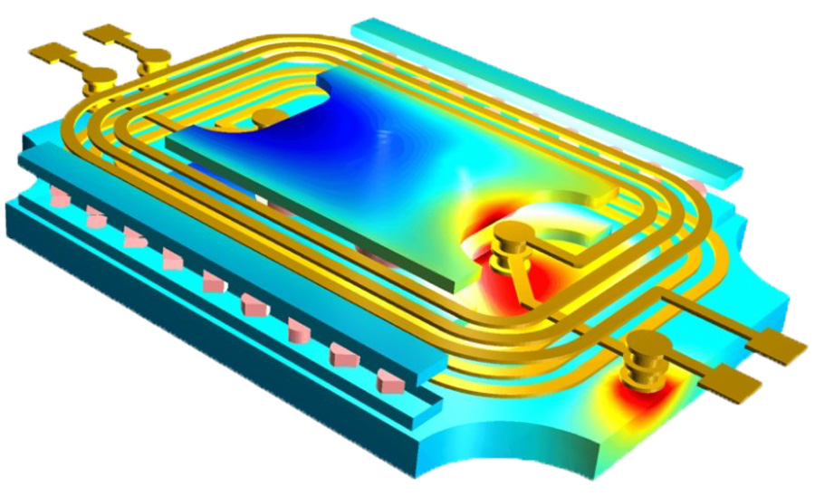
PCB Planar Transformer
The planar transformer is special designed for low profile & low loss but high power application. Compared with traditional toroidal transformer, laminated core transformer, etc., the planar transformer can be through-hole mounted to the board, or can be integrated into PCB directly , thus the low-profile transformer that could handle a range of current values work. A PCB with traces to from the winding creates the planar form factor. The advantage including:
ultra compact flat structure
These PCB planar transformer are much thinner than other similar specs transformers, with sleek design of thin enclosures.
good heat conduction performance
Thin planar transformer over a wider area maybe request more board space, but more excellent heat dissipation during operation.
high power density & less AC loss & repeatable leakage inductance
Planar PCB transformer compact design reduce leakage inductance, with higher power density & efficiency, typical values even reach 99%.
less AC loss
Low stray intra-winding capacitance
The planar transformer stray capacitance within a winding quite low, because inputs & outputs far from each other on the board.

Customized Planar Transformer Design Suppor ted:
Optimal power range: 500W - 50kW
Maximum rated current: 200A Max
Optimum frequency range: 60–500 KHz
Installation mode: perforated installation (THT)
Topology: full bridge, full bridge (ZVS), half bridge, half bridge (ZVS), push-pull, resonance, flyback
During design a planar transformer, following points needed to be considered carefully:
Limitation of current capacity
As planar traces form winding, the design request to ensure sufficiently low-temperature rise.High current limitation ask for more board space during design.
Limitation of current turns ratio
Different current ratings request different trace, PCB size maybe limited your planar transformer's footprint size.
High tooling cost
Not like standard transformer with readily available materials, the planar transformers request putting the components through the standard PCB fabrication process.
High stray inter-winding capacitance
The stray capacitance between windings can be rather high due to the arrangement of coils on different layers of the PCB.
More details, please contact Coilcore directly.
Previous :
Talk About CMC and EMCNext :
Soft Magnetic Transformers & Cores for Charging PilesCategories
New Blog
 Call At :
Tel : +86-20-85649266
Fax : +86-20-85649263
 Email Us :
Email : derful@coilcore.com
 Address :
A402 Zhuangyuangang Industry Park, No.186 Qishan Road, Tianhe District, Guangzhou 510663
© Copyright: 2025 Guangzhou Amorphous Electronic Technology Co.,ltd. All Rights Reserved. 粤ICP备2021057165号

IPv6 network supported